Difference between revisions of "Main House Electricity System"
(Created page with "Deep cycle battery system in the main house The main house has a 24 Volt [V] battery system with a capacity of 420 Ampere-hours [Ah]. The battery system consists of four dee...") |
|||
| (43 intermediate revisions by 5 users not shown) | |||
| Line 1: | Line 1: | ||
| − | + | The electricity system consists of a set of four deep cycle batteries, an inverter, the [[Main 1000 W Solar System]], one 250 W solar panel, an MPPT charge controllers for the five solar panels, a 70 W [[Micro Hydro Turbine]], and a diversion controller. | |
| − | + | [[File:Power_system_layout.png|1200px]] | |
| − | |||
| − | As with all deep cycle batteries, they shouldn’t be drained to less than 20% of their capacity, which results in a usable capacity of 336 Ah with 24 V (~8,000 Watt-hours [Wh]) after purchase. | + | |
| + | # Solar panels and MPPT charge controller | ||
| + | |||
| + | There are five [SUNGOLDPOWER 24V Monocrystalline 200W Solar Panels](https://sungoldpower.com/collections/monocrystalline-solar-panel/products/200-watt-monocrystalline-solar-panel#specification_1)(62.2 x 31.8 x 1.4 inches) that are connected in parallel, which keeps their voltage at 24 V and adds up their amperage. On a sunny day, they output up to 750 W to the [SolarEpic 4215BN MPPT Solar Charge Controller](https://solarepic.com/products/solarepic-mppt-40a-solar-charge-controller-150v-pv-input-tracer-4215bn?variant=12497866457137) ([manual](https://www.epsolarpv.com/upload/file/1903/Tracer-BN-SMS-EL-V1.2.pdf)). The charge controller is rated for 40 A. | ||
| + | |||
| + | The additional, older 250 W panel is connected to a small PWM charge controller. Note that PWM charge controllers are less efficient than MPPT controllers. | ||
| + | |||
| + | For more information on the solar panel upgrade that was done, please refer to [[Additional Solar Panels Research]]. | ||
| + | |||
| + | ### Wires and connectors | ||
| + | |||
| + | We are using around 100 feet of 2 AWG copper cable for each positive and negative connection. The cables are NOT fully water-resistant. Ideally, we should bury them in PVC pipes underground. The SUNDGOLDPOWER panels used to have standard MC4 connectors that we cut off. | ||
| + | |||
| + | ### Mounts and brackets | ||
| + | [SunWize](https://www.sunwize.com/application-item/solar-panel-mounts/) has a large number of solar panel connectors and brackets. [Solar Electric](https://www.solar-electric.com/residential/panel-mounts-trackers/pole-mounts.html) has pole mounts. | ||
| + | |||
| + | __Angles for mounting__: | ||
| + | - February 5th – Set to same angle as your latitude. | ||
| + | - May 5th – Set at the same angle as your latitude minus 15 degrees. At noon the panel will be almost horizontal to the ground. | ||
| + | - August 5th – Set at the same angle as your latitude. | ||
| + | - November 5th – Set at the angle of latitude plus 15 degrees. This tilts your panels towards the sun as it travels low in the southern sky during the winter. | ||
| + | |||
| + | _Our latitude is 36.4037°_. | ||
| + | |||
| + | # Micro-Hydro and diversion controller | ||
| + | |||
| + | The [[Micro Hydro Turbine]] system outputs around 60-110 W all day long. We currently don't have any accurate information on its original efficiency, head, or other characteristics. Please update this section and the micro-hydro page if you know more. | ||
| + | |||
| + | As the micro-hydro system charges the batteries 24/7, it is important to prevent overcharging with a diversion controller that redirects the energy to a heating element. The heating element dumps the electricity and converts it into heat. The diversion controller is the C-35 by Schneider ([Manual](http://solar.schneider-electric.com/wp-content/uploads/2014/11/c-series-manual-975-0004-01-02-rev-d_eng.pdf)). | ||
| + | |||
| + | Oftentimes, the micro-hydro system stops working or outputs low power. If that is the case, you might have to flash the generator or remove leaves from the bucket. For more maintenance information go to [[Micro Hydro Turbine]]. | ||
| + | |||
| + | # Meters | ||
| + | |||
| + | The micro hydro input, the small solar panel | ||
| + | input, and the overall energy usage output that leads to the inverter are connected to blue watt-meter displays ([Bayite DC 6.5-100V 0-100A LCD Display](https://www.amazon.com/dp/B013PKYILS/ref=cm_sw_r_cp_api_fab_QHpEFb372H267)). The meters are multi-functional and display volts, amps, watts, and watt hours. There is also an option to turn on an alarm when the voltage turns low. | ||
| + | |||
| + | [[File:meter-how-to-connect.jpeg |thumb|This graphic informs you about how to connect the blue watt-meter displays to different inputs and outputs.]] | ||
| + | |||
| + | # Inverter | ||
| + | |||
| + | We have a Xantrex SW Series Inverter/Charger that is rated for 3000 W ([manual](http://www.xantrex.com/documents/Discontinued-Products/SW2512MC-SW4024MC2UserGuide.pdf)). | ||
| + | The current inverter's maximum continuous battery charger input is 3600VA. It's maximum alternating current (AC) output overcurrent protection is 35 A at 110 V. | ||
| + | |||
| + | # Deep-Cycle batteries | ||
| + | |||
| + | [[File:12-FS-210 Rolls Battery.JPG|thumb|Deep-cycle battery 12 FS 210 by Rolls Battery]] | ||
| + | The main house has a 24 Volt [V] deep-cycle battery system with a capacity of 420 Ampere-hours [Ah]. | ||
| + | The battery system consists of four deep cycle batteries of the type 12 FS 210 by Rolls Battery ([data sheet](https://rollsbattery.com/wp-content/uploads/batteries/12FS210.pdf)). Each individual battery has an output voltage of 12 V and a capacity of 210 Ah at a discharging rate of 20 hours (please check datasheets for lower discharging rates). The four batteries are parallel- and series-connected, which doubles the system’s voltage and capacity. | ||
| + | |||
| + | [[File:Batteriesinseriesandparallel.JPG|border|thumb|Four 12V batteries in series and parallel]] | ||
| + | |||
| + | As with all deep cycle batteries, they shouldn’t be drained to less than 20% of their capacity, which results in a usable capacity of 336 Ah with 24 V (~8,000 Watt-hours [Wh]) after purchase. Please note that these numbers will be lower after long-term usage. Based on experience, the batteries are severely damaged resulting in a capacity of approx. 40% (3,200 Wh). | ||
| + | |||
| + | ### Charging tips | ||
| + | |||
| + | __Always fill the battery with water before charging.__ | ||
| + | |||
| + | The most dangerous lead acid battery would be a flooded battery with most of the water gone, which maximizes the amount of stored gas possible. When the battery is filled with water there isn't much volume to store the hydrogen. And, of course, the battery will be happier and give more capacity when topped off. | ||
| + | |||
| + | Most of the reported lead acid battery explosions are caused by charging a flooded automotive battery outside the car with an unregulated battery charger. In this case the battery can be left on charge for a long time, and the unregulated charger can run it out of water. Chargers that are designed for battery tending or maintenance , as well as most of the PowerStream lead acid chargers can be left on the battery forever without causing them to gas. Simple, old fashioned, or unregulated transformer chargers should not be left on the battery after it is charged.[^powerstream] | ||
| + | |||
| + | ## Upgrading the batteries | ||
| + | |||
| + | One should refrain from adding new batteries to an already used set as it wears down the old batteries faster. This will result in deep discharged old batteries. Therefore, we could consider moving the current/old set to our future octagonal cabins. As depicted in the illustration above, we could run two independent 12 V systems in different locations. Rolls Battery released a new version of our current batteries, the S12 185 ([data sheet](https://www.rollsbattery.com/battery/s12-185/?pdf=8512)). Here is a [summary of the model updates](https://rollsbattery.com/wp-content/uploads/2019/05/Model-Updates.pdf). | ||
| + | |||
| + | ## Software and hardware | ||
| + | |||
| + | The Main House Electricity System is connected to an Arduino-based [[Electrical Control Unit]]. Please refer to the aforementioned page for the GitHub repository. | ||
| + | |||
| + | # Generators | ||
| + | |||
| + | The large, yellow generator behind the house is used to charge the batteries through the inverter whenever the battery voltage is low. The champion 3650 generator ([manual](https://y79961nbs4u2hvbnwronx9zx-wpengine.netdna-ssl.com/wp-content/uploads/2017/08/100216-om-english.pdf )) can supply up to 3650 watts. However, it will be much happier around 1000 watts. You can set the charging amps on the inverter. We recommend no more than 6 A (around 700 watts) for charging the batteries. | ||
| + | |||
| + | # References | ||
| + | |||
| + | [^powerstream]:https://www.powerstream.com/how-to-use-a-battery-charger.htm | ||
Latest revision as of 01:41, 28 February 2021
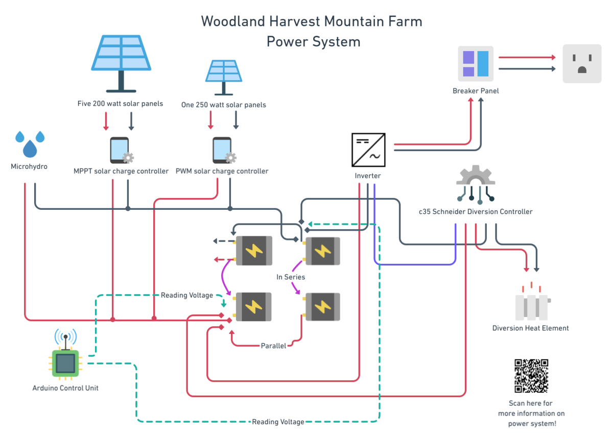
The electricity system consists of a set of four deep cycle batteries, an inverter, the Main 1000 W Solar System, one 250 W solar panel, an MPPT charge controllers for the five solar panels, a 70 W Micro Hydro Turbine, and a diversion controller.
Contents
Solar panels and MPPT charge controller
There are five SUNGOLDPOWER 24V Monocrystalline 200W Solar Panels(62.2 x 31.8 x 1.4 inches) that are connected in parallel, which keeps their voltage at 24 V and adds up their amperage. On a sunny day, they output up to 750 W to the SolarEpic 4215BN MPPT Solar Charge Controller (manual). The charge controller is rated for 40 A.
The additional, older 250 W panel is connected to a small PWM charge controller. Note that PWM charge controllers are less efficient than MPPT controllers.
For more information on the solar panel upgrade that was done, please refer to Additional Solar Panels Research.
Wires and connectors
We are using around 100 feet of 2 AWG copper cable for each positive and negative connection. The cables are NOT fully water-resistant. Ideally, we should bury them in PVC pipes underground. The SUNDGOLDPOWER panels used to have standard MC4 connectors that we cut off.
Mounts and brackets
SunWize has a large number of solar panel connectors and brackets. Solar Electric has pole mounts.
Angles for mounting: - February 5th – Set to same angle as your latitude. - May 5th – Set at the same angle as your latitude minus 15 degrees. At noon the panel will be almost horizontal to the ground. - August 5th – Set at the same angle as your latitude. - November 5th – Set at the angle of latitude plus 15 degrees. This tilts your panels towards the sun as it travels low in the southern sky during the winter.
Our latitude is 36.4037°.
Micro-Hydro and diversion controller
The Micro Hydro Turbine system outputs around 60-110 W all day long. We currently don't have any accurate information on its original efficiency, head, or other characteristics. Please update this section and the micro-hydro page if you know more.
As the micro-hydro system charges the batteries 24/7, it is important to prevent overcharging with a diversion controller that redirects the energy to a heating element. The heating element dumps the electricity and converts it into heat. The diversion controller is the C-35 by Schneider (Manual).
Oftentimes, the micro-hydro system stops working or outputs low power. If that is the case, you might have to flash the generator or remove leaves from the bucket. For more maintenance information go to Micro Hydro Turbine.
Meters
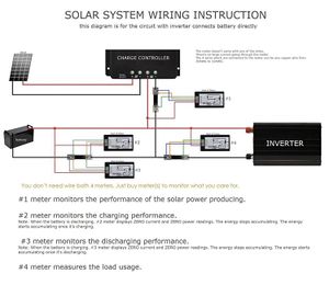
The micro hydro input, the small solar panel input, and the overall energy usage output that leads to the inverter are connected to blue watt-meter displays (Bayite DC 6.5-100V 0-100A LCD Display). The meters are multi-functional and display volts, amps, watts, and watt hours. There is also an option to turn on an alarm when the voltage turns low.
Inverter
We have a Xantrex SW Series Inverter/Charger that is rated for 3000 W (manual). The current inverter's maximum continuous battery charger input is 3600VA. It's maximum alternating current (AC) output overcurrent protection is 35 A at 110 V.
Deep-Cycle batteries
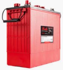
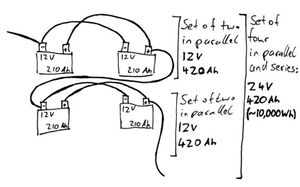
The main house has a 24 Volt [V] deep-cycle battery system with a capacity of 420 Ampere-hours [Ah]. The battery system consists of four deep cycle batteries of the type 12 FS 210 by Rolls Battery (data sheet). Each individual battery has an output voltage of 12 V and a capacity of 210 Ah at a discharging rate of 20 hours (please check datasheets for lower discharging rates). The four batteries are parallel- and series-connected, which doubles the system’s voltage and capacity.
As with all deep cycle batteries, they shouldn’t be drained to less than 20% of their capacity, which results in a usable capacity of 336 Ah with 24 V (~8,000 Watt-hours [Wh]) after purchase. Please note that these numbers will be lower after long-term usage. Based on experience, the batteries are severely damaged resulting in a capacity of approx. 40% (3,200 Wh).
Charging tips
Always fill the battery with water before charging.
The most dangerous lead acid battery would be a flooded battery with most of the water gone, which maximizes the amount of stored gas possible. When the battery is filled with water there isn't much volume to store the hydrogen. And, of course, the battery will be happier and give more capacity when topped off.
Most of the reported lead acid battery explosions are caused by charging a flooded automotive battery outside the car with an unregulated battery charger. In this case the battery can be left on charge for a long time, and the unregulated charger can run it out of water. Chargers that are designed for battery tending or maintenance , as well as most of the PowerStream lead acid chargers can be left on the battery forever without causing them to gas. Simple, old fashioned, or unregulated transformer chargers should not be left on the battery after it is charged.1
Upgrading the batteries
One should refrain from adding new batteries to an already used set as it wears down the old batteries faster. This will result in deep discharged old batteries. Therefore, we could consider moving the current/old set to our future octagonal cabins. As depicted in the illustration above, we could run two independent 12 V systems in different locations. Rolls Battery released a new version of our current batteries, the S12 185 (data sheet). Here is a summary of the model updates.
Software and hardware
The Main House Electricity System is connected to an Arduino-based Electrical Control Unit. Please refer to the aforementioned page for the GitHub repository.
Generators
The large, yellow generator behind the house is used to charge the batteries through the inverter whenever the battery voltage is low. The champion 3650 generator (manual) can supply up to 3650 watts. However, it will be much happier around 1000 watts. You can set the charging amps on the inverter. We recommend no more than 6 A (around 700 watts) for charging the batteries.


