Difference between revisions of "Electrical Control Unit"
| (20 intermediate revisions by 2 users not shown) | |||
| Line 1: | Line 1: | ||
| − | Please refer to | + | The electrical control unit is a wireless communication system that monitors the battery voltage and broadcasts other information. Please refer to the [GitHub Repository "WoodlandHarvestControlSystem"](https://github.com/LSanten/WoodlandHarvestControlSystem) for the code for all Arduinos. The over-the-air communication works on the LoRa system at 915 Mhz.</br> |
| − | # Repository | + | If you feel lost regarding working with any sensors or boards used in the system, check Useful Guides section at the bottom of this page.</br> |
| + | __Feel free to change the code on the Arduinos and platforms. Visitors and students can get editing access to the repository from Leon Santen or Odalys Benitez.__ | ||
| + | |||
| + | #LoRa Network | ||
| + | |||
| + | On the Arduinos that are integrated into the system, we use the [Dragino LoRa shield](https://wiki.dragino.com/index.php?title=Lora_Shield). In the image below, you can see how the pins on the Dragino LoRa shield are assigned. This is useful as not all pins on the shield are useable. This is especially important on Arduino Unos that don't have as many pins as the Arduino Megas.</br> | ||
| + | [[File:Lora board.JPG|500px]]</br> | ||
| + | _The Dragino LoRa shield. Blue-boxed pins are not used by the shield and are free to be used._ | ||
| + | |||
| + | ## Nodes | ||
| + | |||
| + | The following nodes are curently in use: | ||
| + | |||
| + | ### master-arduino | ||
| + | |||
| + | The master Arduino measures the battery voltage with the [Adafruit INA260](https://www.adafruit.com/product/4226?gclid=Cj0KCQiA4feBBhC9ARIsABp_nbUfI0ajLIOyZSA2bku_JZfo73gYy_W1wFGoZthBykCbWl1sPe3xmiYaAnboEALw_wcB) and broadcasts information wirelessly to the other Arduinos. The wireless system uses the [[LoRa research|LoRa protocol]] to communicate at 915 Mhz. For detailed information on what LoRa is and how it works, please refer to the [[LoRa research]] page. The diagram for states and communication codes is on [Whimsical](https://whimsical.com/rf-states-and-communication-codes-TEZgio2TPLtG5tm47541Hq). The prior link redirects you to the diagram. | ||
| + | |||
| + | Purpose:</br> | ||
| + | - Sense and broadcast battery voltage | ||
| + | |||
| + | Data transmission:</br> | ||
| + | - _float_ of battery voltage | ||
| + | |||
| + | ### client_arduino_responsive-light | ||
| + | [[File:GlowingBucket.jpeg|250px]]</br> | ||
| + | _The glowing crystal indicates the batterie's charge status._ | ||
| + | </br> | ||
| + | |||
| + | Purpose:</br> | ||
| + | - Receive battery voltage and change colors to indicate battery status | ||
| + | |||
| + | Data transmission:</br> | ||
| + | - NA | ||
| + | |||
| + | #### Color legend | ||
| + | |||
| + | - >= 27 V | Violet | ||
| + | - between 25 and 27 V | __Green__ | ||
| + | - between 24.3 and 25 V | __Orange__ | ||
| + | - < 24.3 V | __Red__ | ||
| + | |||
| + | |||
| + | # Repository sections - coding comments | ||
| + | |||
| + | _In this section, code-specific comments and tips can be written down for future collaboration if comments in the code don't feel appropriate._ | ||
## master-arduino | ## master-arduino | ||
| − | ## | + | ## client_arduino_responsive-light |
| + | This unit receives the battery voltage from the master Arduino in the mudroom. Based on the voltage, the LED crystal shines in different colors. | ||
## anemometer | ## anemometer | ||
| − | + | We are using a Vortex wind sensor. One revolution per second equals 2.5 mph. Since our anemometer has a relay (a mechanical switch), it creates a _switch bounce_. Therefore, we need a debounce circuit.</br> | |
| − | We are using a Vortex wind sensor. One revolution per second equals 2.5 mph. Since our anemometer has a relay (a mechanical switch), it creates a _switch bounce_. Therefore, we need a debounce circuit. | + | [[File:WindSpeed Porch Oct14.jpg|500px]] |
| − | [[File:WindSpeed Porch Oct14.jpg| | ||
| − | + | _A bug with the current code seems to be related to saving the dateTime string. The dateTime string is saved incorrectly when there should be a trailing 0 in front of the minute reading. I believe that the current code does not include an additional 0 to save minute readings below 10._ | |
# Opportunities to improve the system | # Opportunities to improve the system | ||
| − | - We are currently supplying power to the Arduinos via USB. If we | + | - We are currently supplying power to the Arduinos via USB. If we use efficient Buck converters from the batteries to the Arduinos, we might save some electricity. |
| + | - install a gateway for a LoRa WAN network | ||
| + | |||
| + | # Helpful tools and guides | ||
| − | # | + | ## Tools |
| + | |||
| + | The [falstad online circuit simulator](https://www.falstad.com/circuit/circuitjs.html) is great to quickly test a circuit, check its output voltage or behavior. | ||
| + | |||
| + | ## Guides and tips | ||
__Real Time Clock Setup for SD3231__ | __Real Time Clock Setup for SD3231__ | ||
| Line 37: | Line 88: | ||
How to connect several [SPI devices to Arduino](http://www.learningaboutelectronics.com/Articles/Multiple-SPI-devices-to-an-arduino-microcontroller.php). | How to connect several [SPI devices to Arduino](http://www.learningaboutelectronics.com/Articles/Multiple-SPI-devices-to-an-arduino-microcontroller.php). | ||
| + | |||
| + | __Non-invasive AC Current Sensor ANSANE SCT-013-030__ | ||
| + | |||
| + | Outputs approximately 1 V for every 30 A. | ||
| + | |||
| + | __LoRa Overview on Digikey__ | ||
| + | |||
| + | https://www.digikey.com/en/maker/blogs/introduction-to-lora-technology | ||
| + | |||
| + | __Voltage measuring with voltage divider circuit__ | ||
| + | |||
| + | For precise voltage measurements, it is recommended to use `(analogRead(pin) + 0.5) * 5.0 / 1024.0` [^preciseVoltage]. | ||
| + | |||
| + | |||
| + | ## References | ||
| + | |||
| + | [^preciseVoltage]: http://www.skillbank.co.uk/arduino/measure.htm#:~:text=Precise%20voltage%20measurement%20with%20the,number%20between%200%20and%201023. | ||
Latest revision as of 16:12, 13 April 2021
The electrical control unit is a wireless communication system that monitors the battery voltage and broadcasts other information. Please refer to the GitHub Repository "WoodlandHarvestControlSystem" for the code for all Arduinos. The over-the-air communication works on the LoRa system at 915 Mhz.
If you feel lost regarding working with any sensors or boards used in the system, check Useful Guides section at the bottom of this page.
Feel free to change the code on the Arduinos and platforms. Visitors and students can get editing access to the repository from Leon Santen or Odalys Benitez.
Contents
LoRa Network
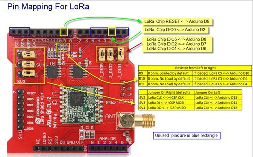
On the Arduinos that are integrated into the system, we use the Dragino LoRa shield. In the image below, you can see how the pins on the Dragino LoRa shield are assigned. This is useful as not all pins on the shield are useable. This is especially important on Arduino Unos that don't have as many pins as the Arduino Megas.
The Dragino LoRa shield. Blue-boxed pins are not used by the shield and are free to be used.
Nodes
The following nodes are curently in use:
master-arduino
The master Arduino measures the battery voltage with the Adafruit INA260 and broadcasts information wirelessly to the other Arduinos. The wireless system uses the LoRa protocol to communicate at 915 Mhz. For detailed information on what LoRa is and how it works, please refer to the LoRa research page. The diagram for states and communication codes is on Whimsical. The prior link redirects you to the diagram.
Purpose:
- Sense and broadcast battery voltage
Data transmission:
- float of battery voltage
client_arduino_responsive-light

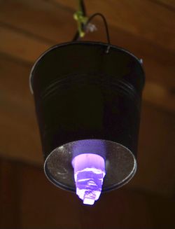
The glowing crystal indicates the batterie's charge status.
Purpose:
- Receive battery voltage and change colors to indicate battery status
Data transmission:
- NA
Color legend
- >= 27 V | Violet
- between 25 and 27 V | Green
- between 24.3 and 25 V | Orange
- < 24.3 V | Red
Repository sections - coding comments
In this section, code-specific comments and tips can be written down for future collaboration if comments in the code don't feel appropriate.
master-arduino
client_arduino_responsive-light
This unit receives the battery voltage from the master Arduino in the mudroom. Based on the voltage, the LED crystal shines in different colors.
anemometer
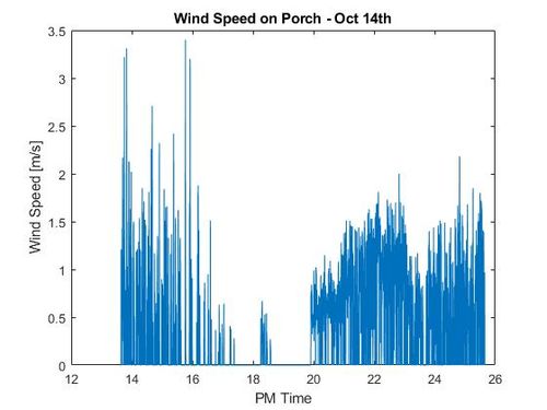
We are using a Vortex wind sensor. One revolution per second equals 2.5 mph. Since our anemometer has a relay (a mechanical switch), it creates a switch bounce. Therefore, we need a debounce circuit.

A bug with the current code seems to be related to saving the dateTime string. The dateTime string is saved incorrectly when there should be a trailing 0 in front of the minute reading. I believe that the current code does not include an additional 0 to save minute readings below 10.
Opportunities to improve the system
- We are currently supplying power to the Arduinos via USB. If we use efficient Buck converters from the batteries to the Arduinos, we might save some electricity.
- install a gateway for a LoRa WAN network
Helpful tools and guides
Tools
The falstad online circuit simulator is great to quickly test a circuit, check its output voltage or behavior.
Guides and tips
Real Time Clock Setup for SD3231
Download DS3231 library on GitHub
Data logging on SD-card
this randomnerdtutorial.com leads you through SD-card usage with an arduino.
Wireless communication with NRF24L01
We have long-run antennas for wireless communication (NRF24L01 Tutorial).
You should solder a 10uf electrolytic capacitor between the power leads.
How to connect several SPI devices to Arduino.
Non-invasive AC Current Sensor ANSANE SCT-013-030
Outputs approximately 1 V for every 30 A.
LoRa Overview on Digikey
https://www.digikey.com/en/maker/blogs/introduction-to-lora-technology
Voltage measuring with voltage divider circuit
For precise voltage measurements, it is recommended to use (analogRead(pin) + 0.5) * 5.0 / 1024.0 1.
