Difference between revisions of "Wind turbine system"
| Line 15: | Line 15: | ||
__Wind direction meter__ </br> | __Wind direction meter__ </br> | ||
| − | ## | + | ## Tower, shaft, bearings |
| + | |||
| + | __Shaft tubes__ | ||
| + | |||
| + | The diameter of the generator's shaft is 1.22 in. It's rated RPM is 360 at 12 m/s. | ||
| + | |||
| + | The shaft consists of an 8 ft section and a 4 ft section of [1.5" OD x 0.134" Wall x 1.232" ID stainless seamless round tube](https://www.onlinemetals.com/en/buy/stainless-steel/1-5-od-x-0-134-wall-x-1-232-id-stainless-round-tube-304-seamless/pid/14789) made out of the 304 stainless steel alloy. The two pieces of the shaft are connected with a slightly wider tube that of [1.75" OD x 0.12" Wall x 1.51" ID](https://www.onlinemetals.com/en/buy/stainless-steel/1-75-od-x-0-12-wall-x-1-51-id-stainless-round-tube-304-welded/pid/483). | ||
| + | |||
| + | __Bearings__ | ||
| + | |||
| + | The shaft is held in place by two [Mounted Ball Bearing with Nickel-Plated Iron Housing | ||
| + | for 1-1/2" Shaft Diameter](https://www.mcmaster.com/6494K19/). | ||
| + | |||
| + | ### Forces on the shaft[^ncyuMaterials] | ||
## Tower | ## Tower | ||
| Line 162: | Line 175: | ||
- averaging periods of 10 min are commonly used; 30 min period for turbulence studies; the larger integral time scale, the larger should be averaging period; sampling frequencies should be much smaller than the integral time scale | - averaging periods of 10 min are commonly used; 30 min period for turbulence studies; the larger integral time scale, the larger should be averaging period; sampling frequencies should be much smaller than the integral time scale | ||
- you have to detrend the time series to get rid of high-frequency fluctuation | - you have to detrend the time series to get rid of high-frequency fluctuation | ||
| + | |||
| + | |||
| + | # References | ||
| + | |||
| + | [^ncyuMaterials]:http://web.ncyu.edu.tw/~lanjc/lesson/C3/class/Chap03-A.pdf | ||
Latest revision as of 19:25, 19 November 2020
Contents
- 1 Current System
- 2 Prototyping
- 3 Research and background knowledge
- 3.1 Tower design
- 3.2 How to charge our batteries
- 3.3 Research papers, articles, media
- 3.3.1 Aerodynamics of vertical-axis wind turbines in full-scale and laboratory-scale experiments
- 3.3.2 Analysis of Different Blade Architectures on small VAWT Performance
- 3.3.3 Small Scale Wind Turbines Optimized for Low Wind Speeds
- 3.3.4 10 Wind Turbines That Push the Limits of Design
- 3.3.5 Design and Manufacture of a Cross-Flow Helical Tidal Turbine
- 3.4 General wind turbine knowledge
- 4 References
Current System
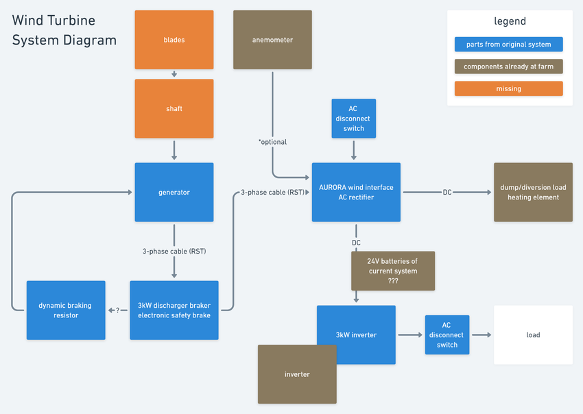
view and comment on system diagram
Equipment manuals
Aurora 3kW inverter - data sheet
Aurora wind interface box/rectifier - manual
TCMG-3kW Taechang N.E.T. Generator - online specs
3kW Discharger Breaker - 3K-DIS-001 - can't find online manual -
3kW Dynamic Braking Resistor - instruction manual
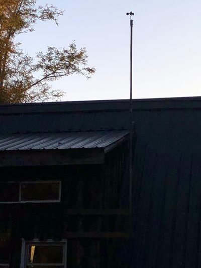
Anemometer
Wind direction meter
Tower, shaft, bearings
Shaft tubes
The diameter of the generator's shaft is 1.22 in. It's rated RPM is 360 at 12 m/s.
The shaft consists of an 8 ft section and a 4 ft section of 1.5" OD x 0.134" Wall x 1.232" ID stainless seamless round tube made out of the 304 stainless steel alloy. The two pieces of the shaft are connected with a slightly wider tube that of 1.75" OD x 0.12" Wall x 1.51" ID.
Bearings
The shaft is held in place by two Mounted Ball Bearing with Nickel-Plated Iron Housing for 1-1/2" Shaft Diameter.
Forces on the shaft1
Tower
Blades
Anemometer - wind speed measuring
We are using a Vortex wind sensor. One revolution per second equals 2.5 mph. Since our anemometer has a relay (a mechanical switch), it creates a switch bounce. Therefore, we need a debounce circuit. Please refer to Electrical Control Unit for the repository and more information.
Prototyping
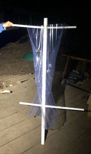
Twisted Savonius V1
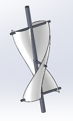
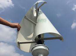
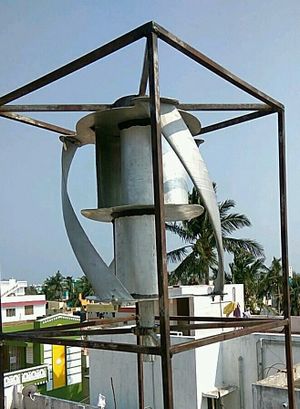
We attempted to prototype a twisted Savonius turbine to allow a more continuous application of force when the wind turbine spins. Ideally, both sails would be slightly offset to each other to allow airflow from one airfoil to the other. Such an offset can be seen in the following picture that inspired our design. As the Savonius turbine is based on drag, it has a high starting torque, which will allow for lower self-starting speeds.
With our next prototype, we seek to combine a twisted Savonius turbine with a Gorlov turbine (Rajdeep Nath Dr. John Rajan; How to Design and Fabricate a Vertical Axis Wind Turbine: Design, Analysis, and Fabrication using Gorlov and Savonius Blades (p. 75)). We can 3D print the blades but might want to scale down the prototype to decrease printing time.
Research and background knowledge
Tower design
We considering building a wooden structure on top of the house to elevate the wind turbine. A tripod design that attaches to the two bump-outs and the gable would make the tower accessible. We are currently considering a tower height of 15 feet up to 22 feet.
Guy wires are an option to secure the turbine as it will be quite large to account for low wind speeds. However, a pole that is merely held up by guy wires is not accessible enough.
How to charge our batteries
We seek to charge our battery system with the energy obtained from the wind turbine. However, our current system diagram connects the AC rectifier to the inverter, which outputs 110 V alternating current (US outlets). As the energy output from the wind turbine will vary quite a lot, we need to charge the batteries with direct current (DC). For that purpose, we might have to acquire a wind turbine battery charge controller that can handle high voltages (0-600 V from the AC rectifier) to charge our 24 V battery system. Tae Chang offers a Battery Charge Controller. We probably need a 600 VDC 24v wind turbine MPPT charge controller 2500W. Most charge controllers seem to be in the range of 200-300 VDC (example), which might be enough considering wind speeds in our area.
Research papers, articles, media
Aerodynamics of vertical-axis wind turbines in full-scale and laboratory-scale experiments
Araya, D. B. (2016). Aerodynamics of vertical-axis wind turbines in full-scale and laboratory-scale experiments (Doctoral dissertation, California Institute of Technology).
Analysis of Different Blade Architectures on small VAWT Performance
Battisti, L., Brighenti, A., Benini, E., & Castelli, M. R. (2016, September). Analysis of different blade architectures on small VAWT performance. In Journal of Physics: Conference Series (Vol. 753, No. 6, p. 062009). IOP Publishing. https://iopscience.iop.org/article/10.1088/1742-6596/753/6/062009/pdf
Small Scale Wind Turbines Optimized for Low Wind Speeds
Letcher, T. (2010). Small scale wind turbines optimized for Low Wind Speeds.
10 Wind Turbines That Push the Limits of Design
https://www.popularmechanics.com/science/energy/a4428/4324331/
Design and Manufacture of a Cross-Flow Helical Tidal Turbine
Anderson, J., Hughes, B., Johnson, C., Stelzenmuller, N., Sutanto, L., & Taylor, B. (2011). Capstone Project Report: Design and Manufacture of a Cross-flow Helical Tidal Turbine. University of Washington, Washington.
General wind turbine knowledge
A lot of these insights are from the Wind Energy Coursera course.
Wind turbine terminology
- rotor - generates aerodynamic torque
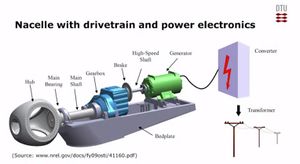
- nacelle - converts torque into electrical power
- tower - hold nacelle and rotor blades
- foundation - hold the whole turbine in place
- VAWT - vertical axis wind turbine
- HAWT - horizontal axis wind turbine
Forces acting on VAWT and HAWT blades
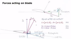
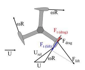
If the vertical axis turbine has blades that use lift to create a net force that spins the turbine, the forces acting on the blade are equivalent to forces on horizontal axis turbines. The aerodynamic forces on the blades are described in the two image to the right.
Wind energy extraction
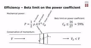
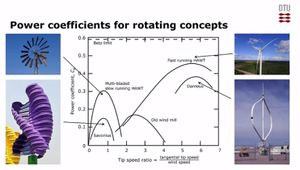
The mechanical power of a turbine can be calculated with the equation to the right. The Betz limit on the power of a fast-spinning wind turbine (59%) describes the maximum energy that a turbine can extract from the wind. Depending on the turbine design, the Betz power coefficient changes. Turbines that are based on lift (not drag) have generally speaking higher coefficients. Please refer to the different Betz based roughly categorized by turbine types to the left.
Rotating lift-based machines - horizontal axis wind turbine, a vertical axis wind turbine with blades (Gorlov or Darrieus)
Rotating drag-based machines - vertical axis turbines - similar to cup anemometer; Savonius (efficiency 10%-15%) could be nice for aesthetically pleasing turbine
Flying lift-based machines - pulls up sail that pulls on a cord that spins spindel
Machines using flow-induced vibrations
Towers types
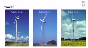
The tower needs to withstand high torque. Metal ropes can be used to keep the top of the tower in place. Furthermore, the foundation needs to be solid and deep.
General tower types:
- tubular towers
- lattice towers
- tripod towers
Financing (for large-scale projects)
Our revenue is the production of net electricity in Wh (Annual Energy Production): Capacity of Farm x 8760h x capacity factor 0.25
1 - Simple payback time (SPT)
Simplistic Calculation
- estimate of annual production in Wh
- annual revenue - production x energy sale price
- annual operating costs
2 - Net present value (NPV)
(revenue - costs) - original investment
if less than 0, probably not profitable
excel has NPV function
3 - Levelised cost of Energy (LCoE)
goal is to find cost per MWh that can be used for comparison:
(Capital Investment + Operational Costs + Decommissioning Cost)/ MWh
Statistical Analysis of Wind Speeds and Turbulence
- Navier-Stokes equation (evolution equation) to calculate wind speeds in space
- statistical analysis, spectra, turbulence intensity is obtained by mean wind speed and standard deviation of wind speeds
- every wavelength (after Fourier transform) can be thought of as a length scale
- wind vector (u, v, w)
- integral length scale; from time series, we compute the auto-correlation function
- turbulence spectra
- averaging periods of 10 min are commonly used; 30 min period for turbulence studies; the larger integral time scale, the larger should be averaging period; sampling frequencies should be much smaller than the integral time scale
- you have to detrend the time series to get rid of high-frequency fluctuation
